

Next: 4 Comparison
Up: Architectural Jigsaw Patterns
Previous: 2.3 Components
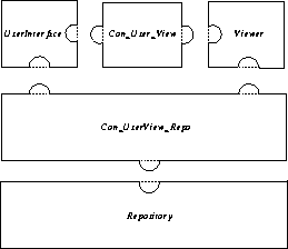
The ``3D-Med'' system is implemented in C++ and Java. The architecture of the prototype ``3D-Med'' system is illustrated in Figure 3. Overall, it contains three components: UserInterface, Viewer and Repository. UserInterface provides user menus and produces corresponding actions according to user interactions. Viewer processes images and produces 3D image views on the screen. Repository is a data base for storing images. Two connectors,  and
and  , connect these three components. Figure 3 gives the graphical presentation of an overview of the system architecture by means of jigsaw patterns .
Figure 3. Overview of the ``3D-Med'' prototype architecture
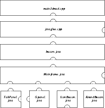
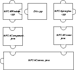
Each component and connector can be taken as a new system and be decomposed in the same notation. Figure 4 illustrates the decomposition of the component UserInterface, and Figure 5 shows the decomposition of the connector  .
.
Figure 4. Decomposition of the component UserInterface
Figure 4 also gives examples of the Application modules. For instance, a standard C++ linkage glues a C++ object in the javaglue.cpp module, and a standard Java linkage glues a Java object in the button.java module.
Figure 5. Decomposition of the connector 
Figure 4 and Figure 5 illustrate how a subsystem is decomposed using jigsaw patterns . In this particular case, components and connectors are expressed in terms of C++ and Java modules. Here we did not specify the interfaces. This could be done by using a header file or the package concept of C++ and Java.


Next: 4 Comparison
Up: Architectural Jigsaw Patterns
Previous: 2.3 Components
Hongyan Sun and Anders P. Ravn
Sept. 2, 1997
![]()
![]()
![]()
![]() and
and ![]() , connect these three components. Figure 3 gives the graphical presentation of an overview of the system architecture by means of jigsaw patterns .
, connect these three components. Figure 3 gives the graphical presentation of an overview of the system architecture by means of jigsaw patterns .


